Mobile 3D Printer Bot
Python | SLAM | Automation | Design | MoveIt | Arm Manipulation | Laser Cut | 3D Print
Fig 1. Constructing two mountable lines
Description
In this project, I assembled a new robotic configuration with different turtlebot parts. The robot is equipped with a custom melting mechanism, which can melt different materials such as wax. As the robot navigates the environment, the dripping wax from the melting mechanism can print different constructions such as ramps, walls, and drawings.
This project was inspired by a Mars habitat building competition, and aimed at developing a fully autonomous mobile 3D printing system. One of the goals of this work was to create a robot that is both reliable and robust and can be easily be used as a tool in real applications besides the margins of this project. Thus, a lot of focus was placed on making the system as robust, precise, safe, and self-sufficient as possible. More specifically, the system should easily map and localize the robot's position, be paused and restarted from different initial conditions, integrate safely with the hot melting mechanism, and perform the printing operations in a real complex-dynamic environment with potential human interference.
Demonstration
In the following videos different usecases of the 3D printing robot are shown, such as drawing a face (Fig.1) contructing two lines which can be mounted (Fig.2), buliding a ramp over some untraversable obstacles (Fig.3).
Fig 2. The robot is drawing an emoji face
Fig 3. Navigating over untraversable objects by building a ramp from wax
Overview
Three main packages were implemented, namely the arm , the bulider , and the brain package. The arm package is responsible for manipulating the PX100 robotic arm using MoveIt. The builder package inlcudes navigating, mapping, localizing and printing with the differential robot. These two packages are entirely independent and do not affect each other. Finally, the brain package is the package that launches everything, controls, and commands what action each robot should take and when.
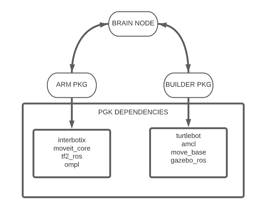
Fig 4. The main architecture of this project.
4DOF Robotic Arm Manipulation
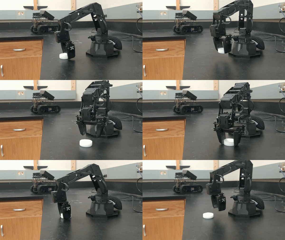
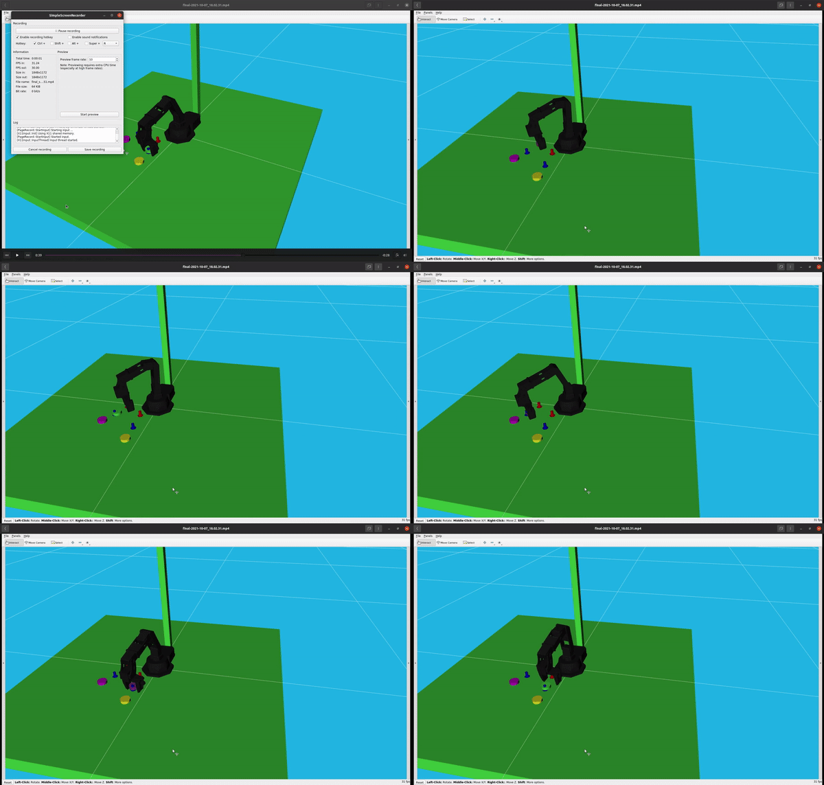
The manipulation functions of the arm are implemented with MoveIt. The arm is tasked with refueling the turtle builder with wax. During operation, the pick and place positions are considered fixed. However, since these positions are changing through the lifetime of the project, we implemented a simple interface to modify/tune them. The used arm robot is a 4 DoF arm but MoveIt operates with full 6-dof goal poses, thus the two orientation parameters (roll, pitch) are always fixed. Furthermore, we also fix the cartesian z parameter since the meltable material (wax) is always picked and placed from the same height. Our simple interface reads the YAML file, which includes two polar coordinates (r, θ) and the yaw parameter, and converts them to a full 6-dof pose. This simple specification makes it easy to find new parameters within 1-2 iterations when changing the environment or setting. Additionally, the implemented nodes add the environment collision objects to the MoveIt scene, including the candle object, which is being attached and detached from the end effector's arm. A standard motion planning algorithm (RRTConnect) is used to plan between the calculated start and goal configurations.
Using this implementation, an example of pick and place is shown below:
Mapping and Localization
The slam toolbox is used for mapping the environment. Using a single launch file at the current implementation, we can easily navigate and create a new map and save it. Making it easy to relocate our construction site to a different place expecting identical behavior.
Below is the real environment and the map generated for it:
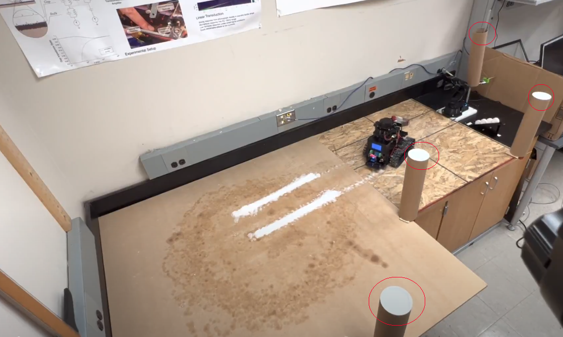
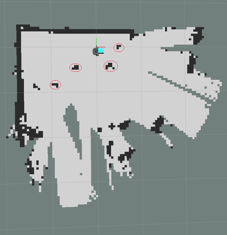
Fig 5. Map of real world
This project is heavily dependent on repetition since we need to repeat the cycle of refuel-print multiple times for hours. Hence we can not count on odometry since there would be accumulative errors for the position. AMCL algorithm is used for localization by tunning his parameters, such as based more on lidar sensor than the odometry for navigating. It is also important to mention that no external system, such as a camera April tag, defines or corrects our position. In order to help the localization algorithm, Placing in the environment some tubes help improve its performance. After tuning and mapping, the system can be placed in any environment and follow its path reliably for hours. Also, changes in the environment, such as humans moving through it or a misplaced cube, do not affect it, and the accuracy is less than a centimeter.
State Machine
In order to fuse everything together, the creation of a state machine is necessary given that there are multiple robots where each one has its actions, services and they need to work together.
State Machine Main Cycle
The most important state machine is the main cycle(see figure 6). This cycle, if simplified, is: go print --> cool down --> refill with wax. The idea is that by repeating this cycle multiple times, eventually, a construction will be made. For simplicity, I did not include them on the diagram. However, extra states that handle aborting the cycle mission or stopping the robot and disabling the heating bed have been implemented for safety reasons, and the program will still be able to resume smoothly.
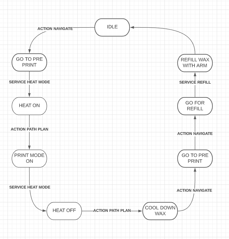
Fig 6. Main Cycle
Navigation Pipeline
Two simple actions have been implemented, path_plan and navigation (see figure 7).
Navigation action simply takes a target position as an input and publishes the corresponding cmd vel in order to go at the desired position.
The path plan action calls the navigation action. Path plan has three different modes line, circle, point. A custom goal message has been created, and through that, various settings are being defined for the path planner. For example, if we want to navigate reverse or forward, position, a line's discrete steps or a semi-circle are defined, repeating time, and many more. Additionally, this action publishes all the rviz messages such as arrows, paths, goal points, etc. Path plan action is the primary action for navigating the turtlebuilder. In addition, the states of print and cool down from the main cycle are the path plan action with different settings.
You can see at figure 2 path planning action performing a face print where first eyes are done (setting points) then mouth (setting line) and finaly a sime-circle and a full circle(setting circle)

Fig 7 Navigation Pipeline
State Machine Brain
On top of the main cycle state machine, another layer has been created controlling the path plan action. With this state machine, we change the settings of the action and be able to define building constructions. Below are two examples (on debug mode), building a ramp and drawing a face.
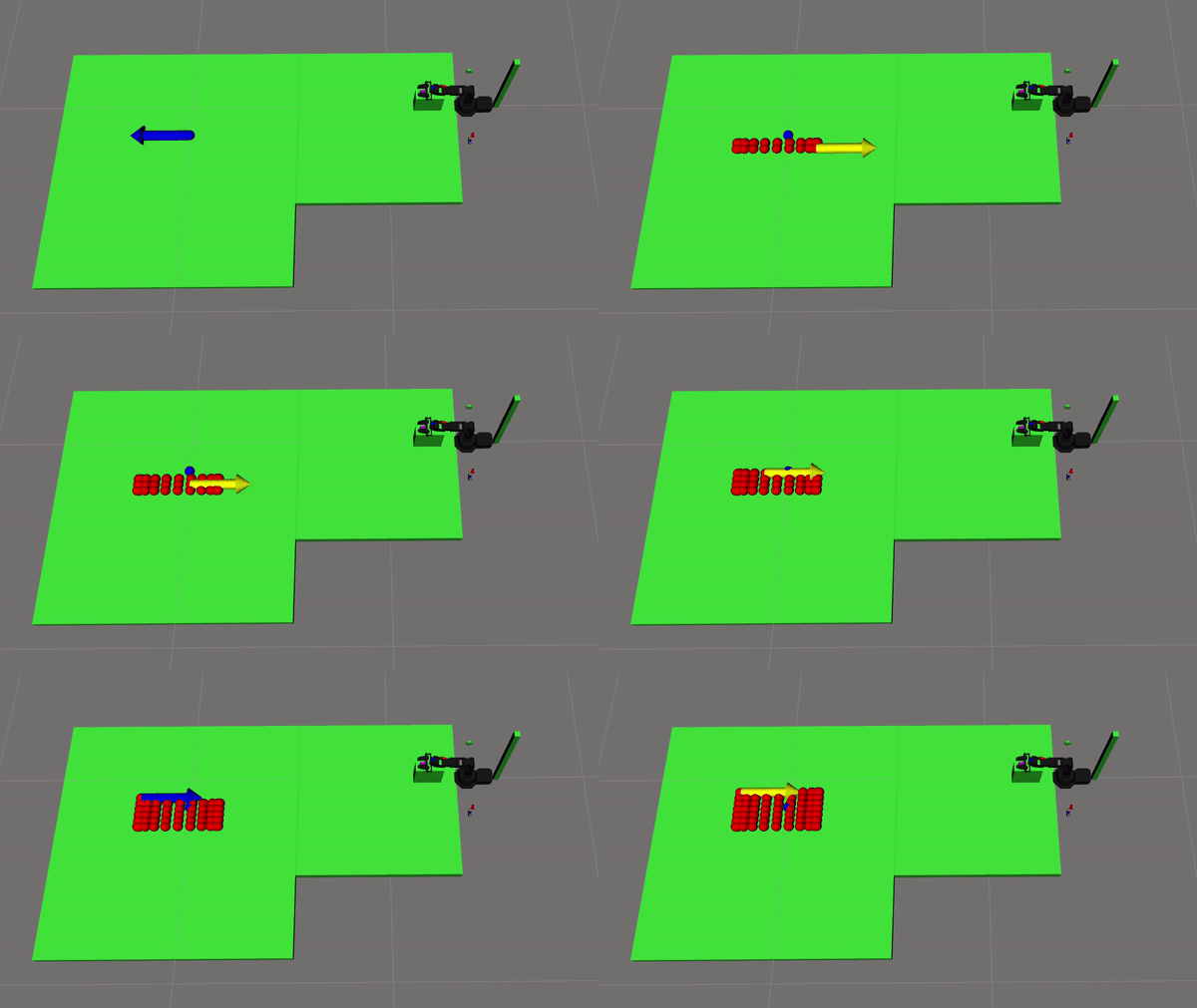
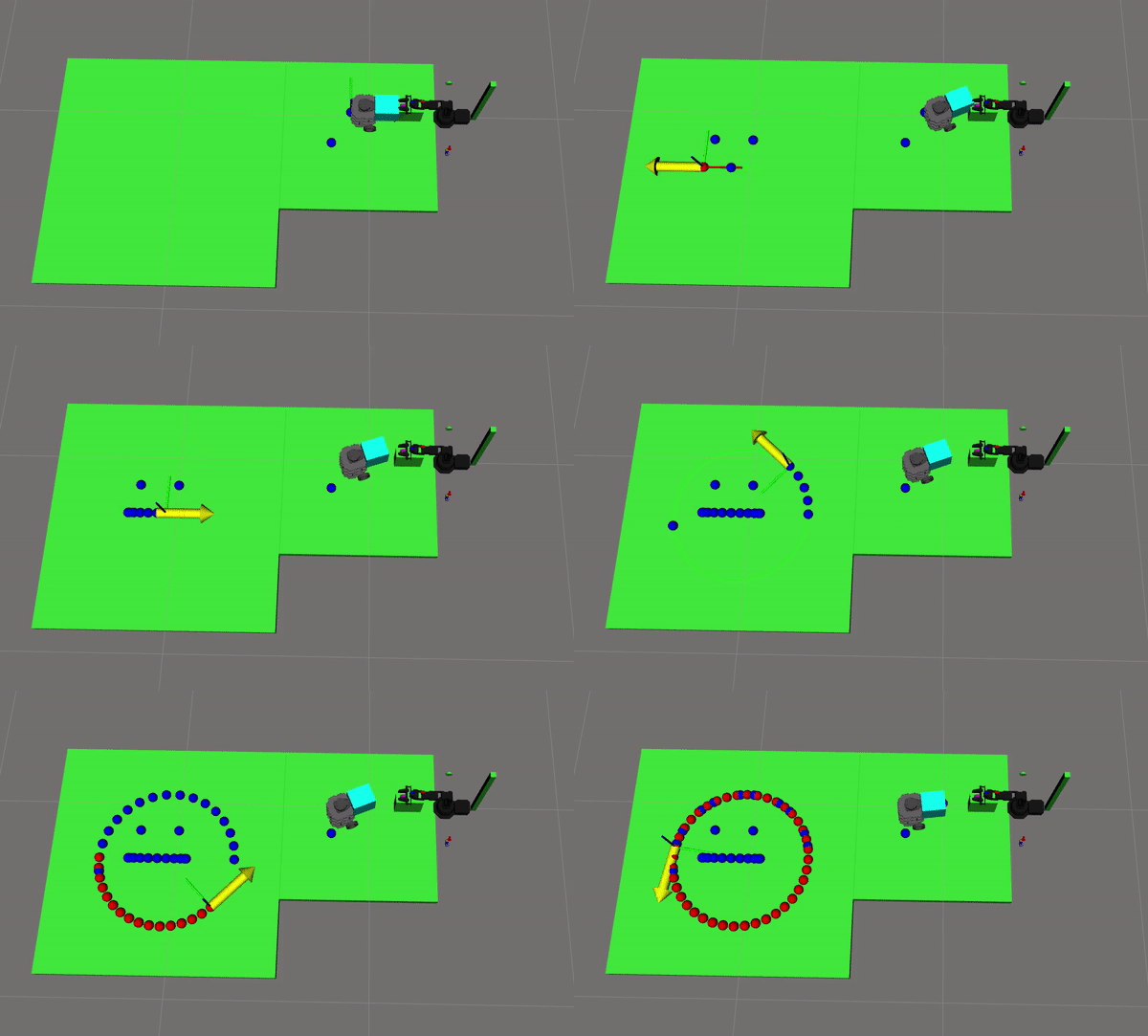
Fig 8. rviz prinnting example
Time manager
Last but not least, a time management node was developed to automate and finalize the printing system fully. Before this node, a human played the role of an instructor giving commands such as repeat printing, deciding when to go for refuel, stopping the cool-down process, etc. Adding this extra controller, the system is fully automated, and a human is only responsible for refilling the wax holder and observing the operation.
Simulation
a Gazebo world was made similar to the actual environment where various tests were made to confirm the code's resilience to noise and unexpected behaviors. For example, since this project is heavily dependent on repetition, A ros node was implemented that adds odometry noise. Confirming that the accumulative error will not affect the localization algorithm and will always correct the position.
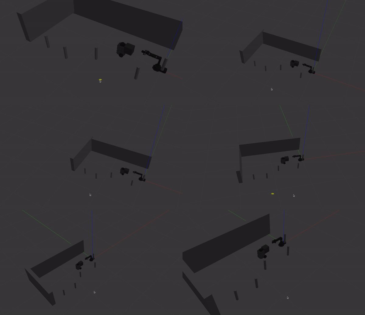
Fig 9. Gazebo Example
Similar to 3D printing, the construction process takes several hours in this project. Therefore before starting a printing process, we need to ensure that the code is correct. Therefore, fake nodes are being used for both robots (robotic arm, builder robot) to rapidly see on rViz where the robot is being commanded to navigate with which direction, etc. Also, markers are essential with colors for different states (print mode on/off) or arrow markers displaying the desired position and direction.
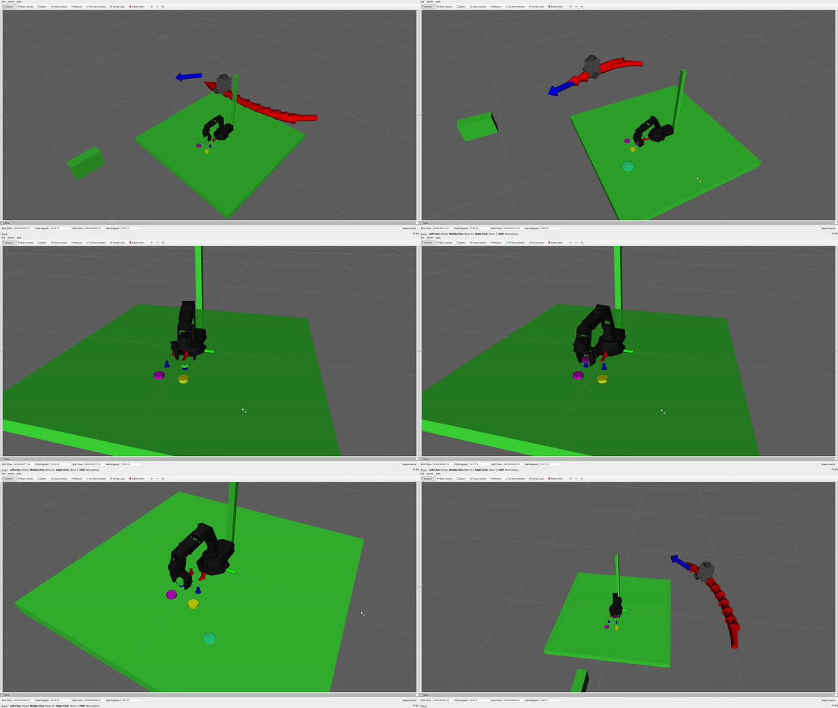
Fig 10. Rviz Example
It is also worth mentioning that using one launch file, we can easily switch between using the actual robot to gazebo simulation or fake nodes or launching only the arm or the builder robot, and everything will be launched correctly with zero error messages or warnings.
Refuell
An essential aspect of this project is automation, and human interference should be limited. Hence a robotic arm with 4 DOF was used to refill the robot with candles. A ros service has been implemented in which the robot will stop printing, shut down the melting mechanism, go in front of the arm and refuel its tank with more wax. The arm's trajectory was implemented using MoveIt, where the environment and the current position of the builder robot are added, ensuring the avoidance of colliding with it or any other object. Also, a slider was designed ( using laser cut) where the arm picks the candles from there one by one. A human is only needed to refill the slider.
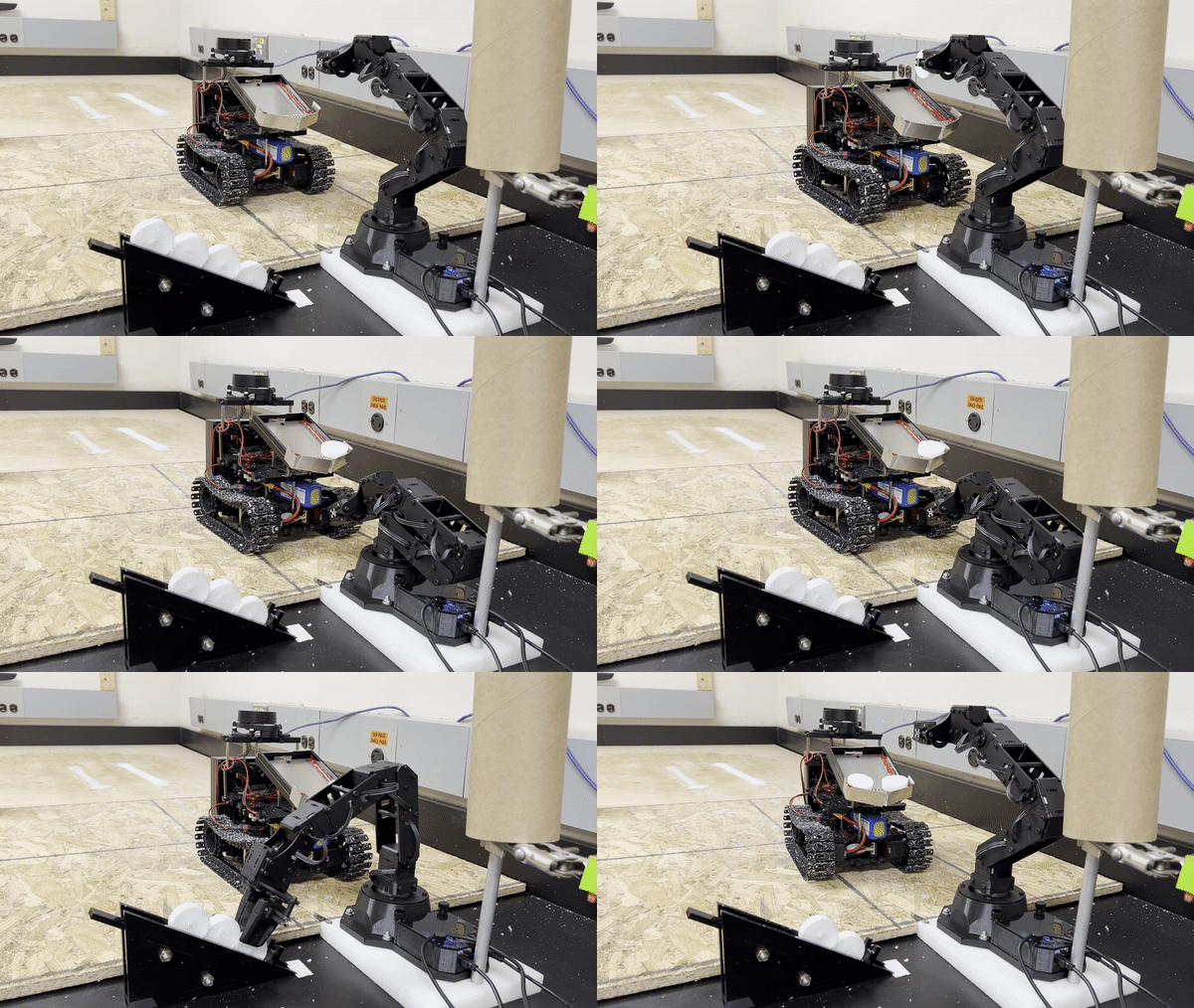
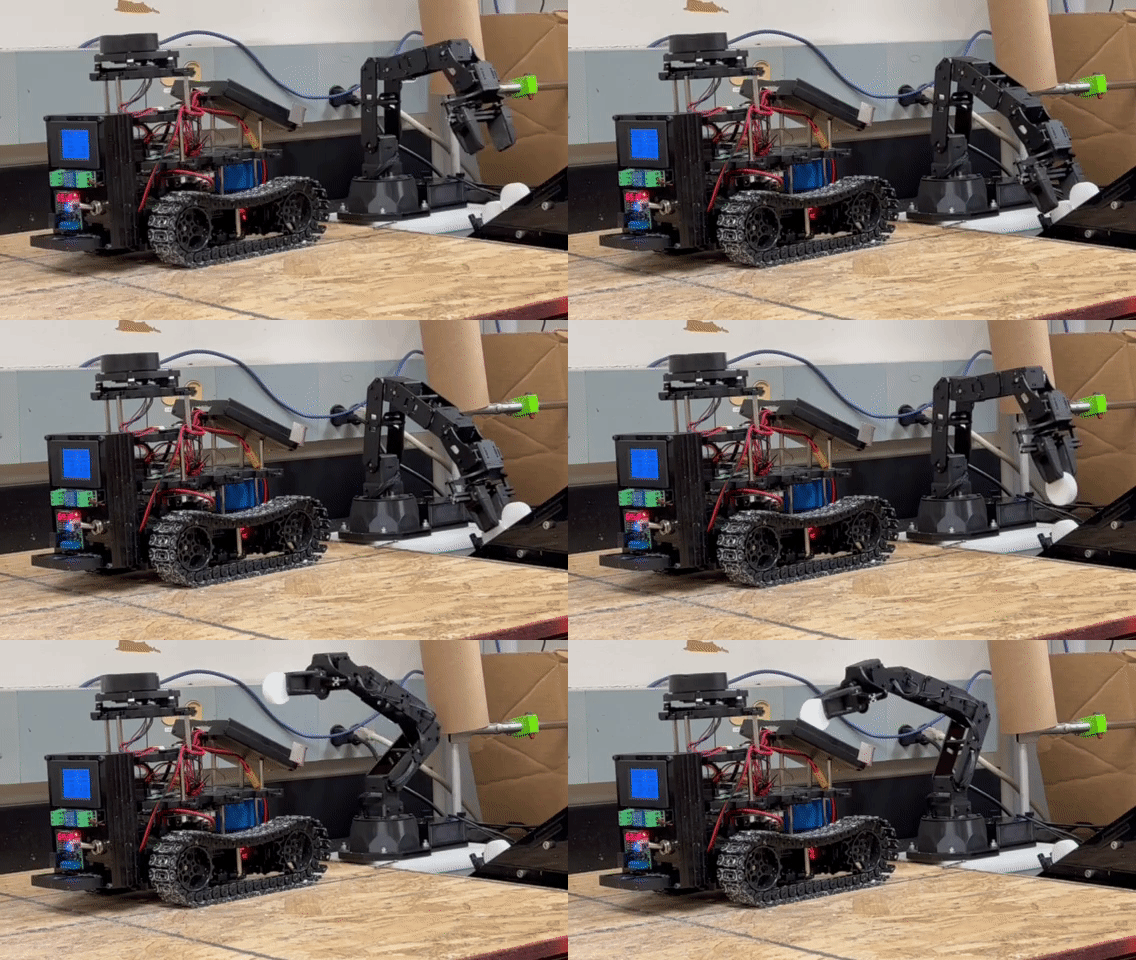
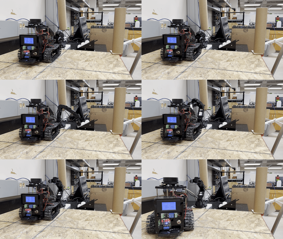
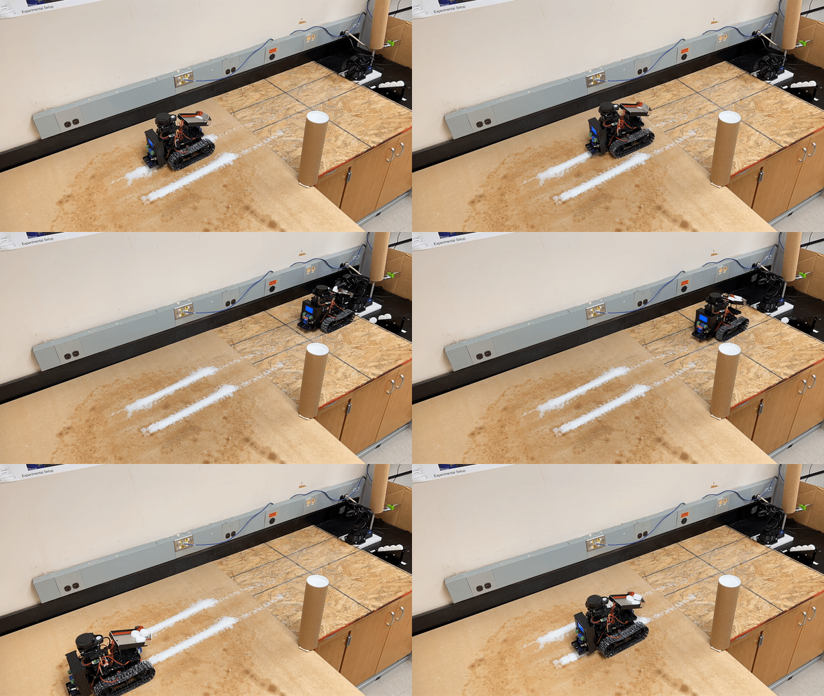
Fig 11. Refilling builder robot using a robotic arm
Disposal Mechanism For Melting Wax
After various iterations of design and experimenting with different nozzles and heating elements, I decided to create a heating bed made out of aluminum and use a flexible polyimide heater plate as the heating element. I waterjet the aluminum and bend it, giving it a shape similar to an arrow with a slot at the end for dripping the wax. I placed the heating elements and a temperature sensor at the back of this arrow-shaped plate. Aluminum was chosen since it can withstand high temperatures and is suitable for heat transfer. Finally, the bed is sealed with heat-resistant silicone, and at the end of the arrow, a spring is placed blocking big chunks of wax, ensuring that the dripping slot is not blocked.
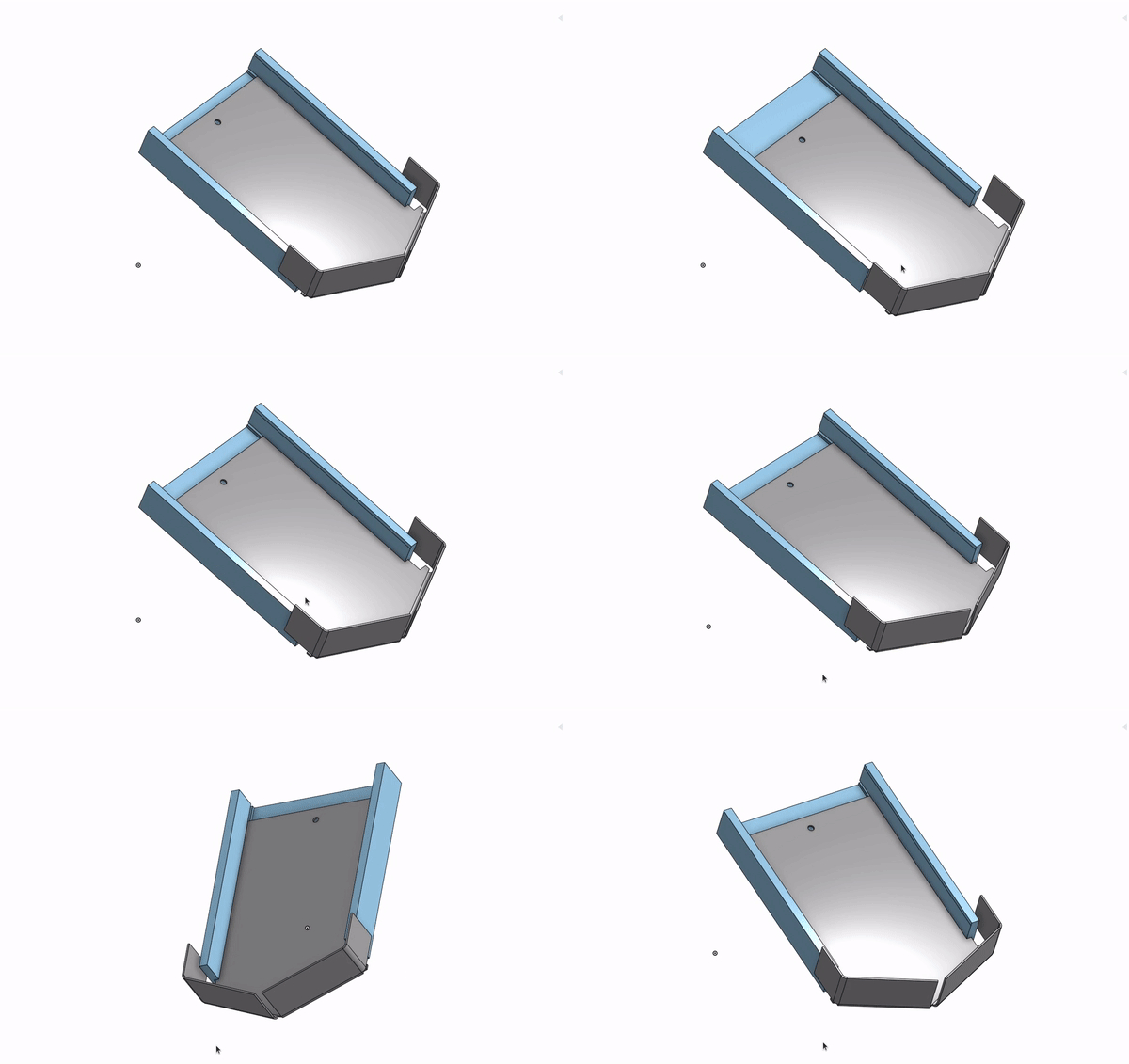
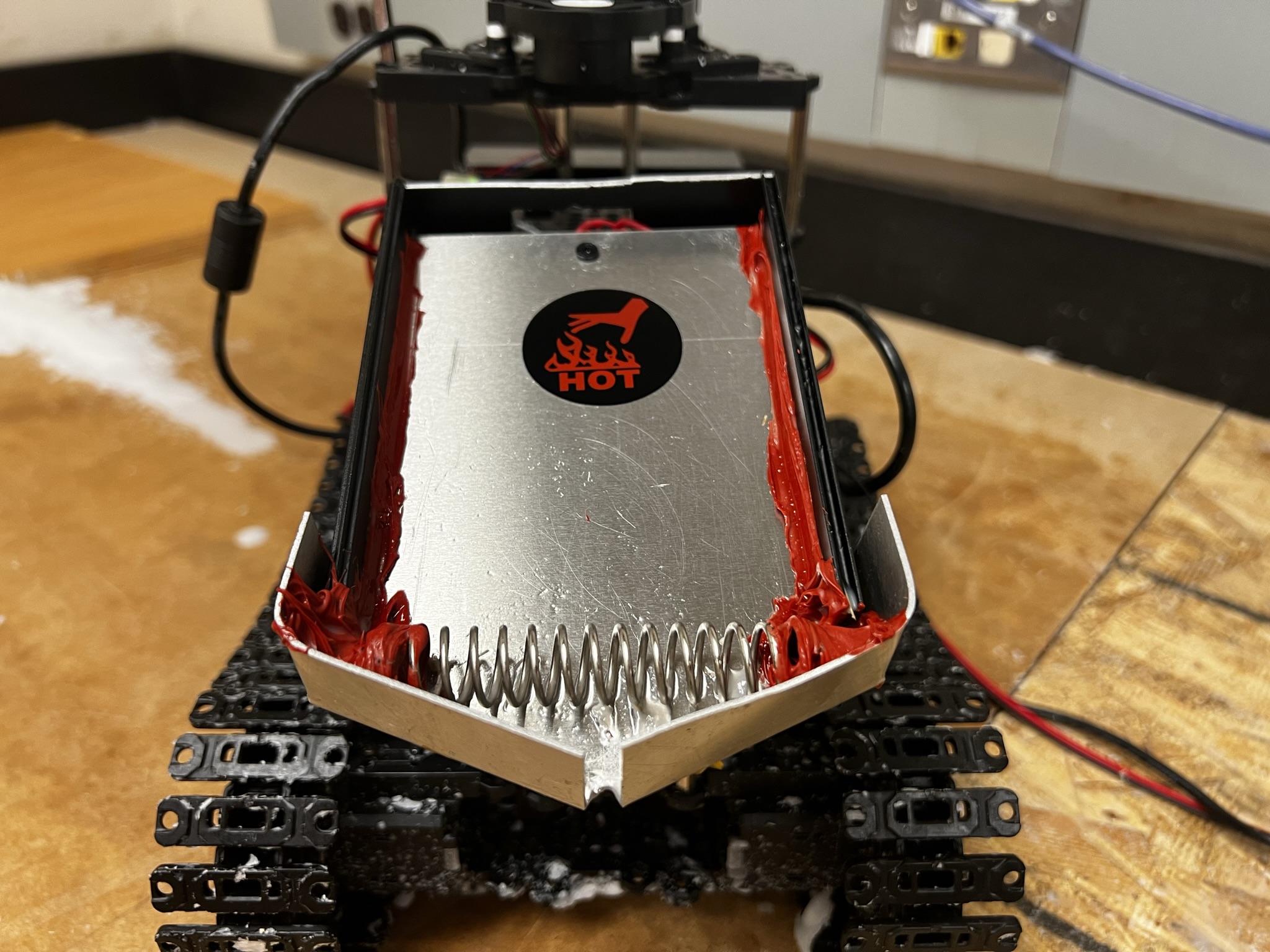
Fig 12. Power Source Control
Power Source Device
In addition to the heating bed, a power source case was designed and made using a lazer cut machine.
In this case we have:
- 3.3V Relay connected at the Rasp for activating the heating system using ROS.
- Temperature display/relay sensor to keep the heating bed within the desired margins and avoid overheating.
- Display showing the current Voltage and consumption on the battery for debugging purposes, such as if we draw current and monitor the battery conditions.
- Two fans connected in series are placed at the front for a faster cooldown of wax.
- on/off switch
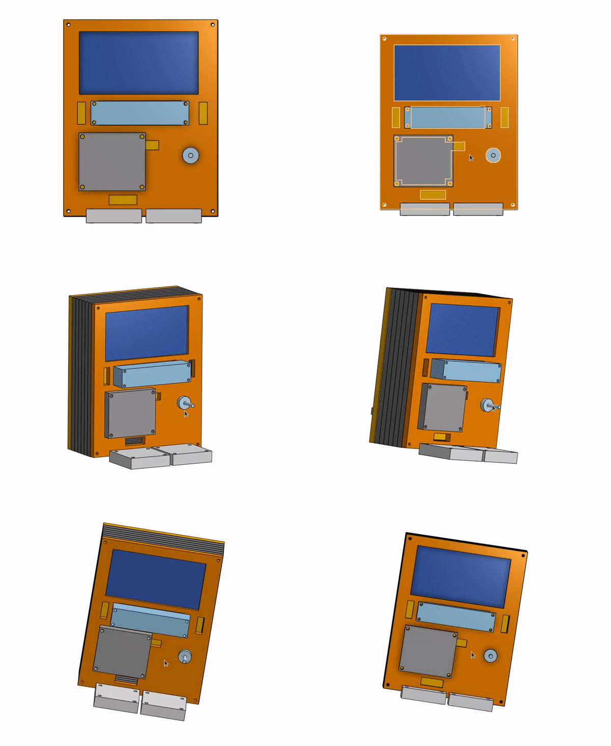
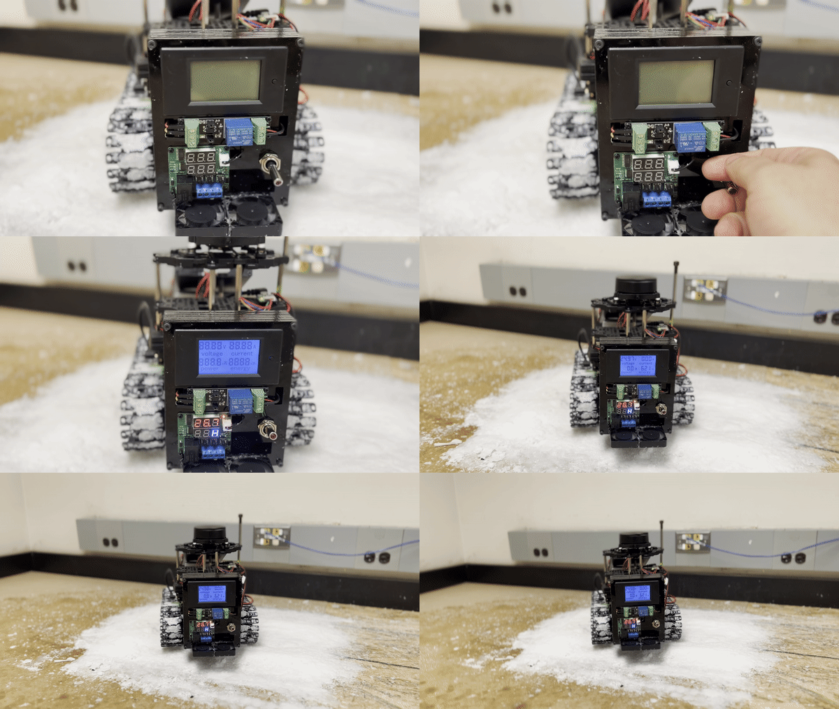
Fig 13 Power Source Control
Recycling
One reason wax is selected as a material is that it can be reused. We can either directly take scrap wax and now use it for printing or recreate the cylinder shape to be used later with the robotic arm.
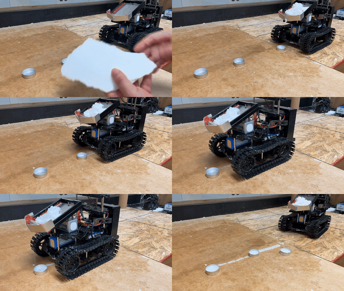
Fig. 14 Recycle wax
Cool Down
The robot is equipped with fans at the front and back to speed up the printing process. The fans drastically decrease the amount of time needed for the wax to cool down, so the builder robot will be able to step on it faster.
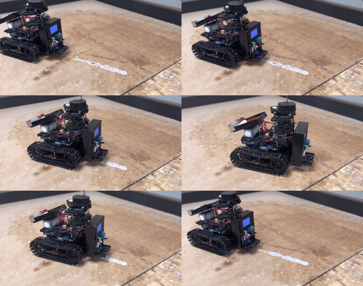
Fig. 15 Cooling wax with fans
Safety
Battery Safety
Lipo batteries have a high chance of starting a fire if not treated correctly. So the first measure is that the robot is equipped with a screen (see left image figure 16). The voltage and current are displayed on the screen to monitor the battery's condition. Also, an extra component (see right image figure 16) is connected directly to the battery, checking each cell of it, and if any cell drops its Volt below a certain threshold, an alarm sound will start.
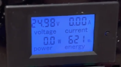
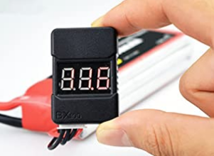
Fig 16 Battery Safety
Hot Surface Safety
For the melting mechanism, a special sticker is placed on it. If the surface of the device is hot, then the sticker appears, indicating that we should not touch it. Also a temperture sensor is being used in order to avoid overheat.
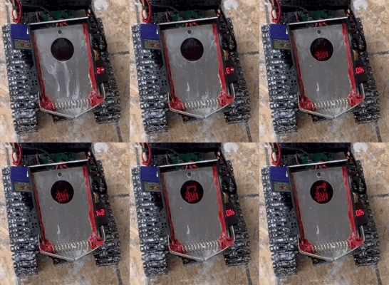
Fig. 17 Hot Surface
Code Safety
The printing environment is done on a table. The chance of the robot falling from the table and getting damaged was severe, especially while developing this project. Hence a ros service was made that will stop the robot. This service would kill necessary nodes, stop various actions and block cmd velocity, ensuring that the robot will stop moving.
Robot Maintance
The printing process is not ideal, leading the caterpillar treads of the robot to get filled with wax after multiple hours of printing. Although this does not affect the performance of the builder robot, below is an example of self-cleaning the treads using a gun that blows hot air.
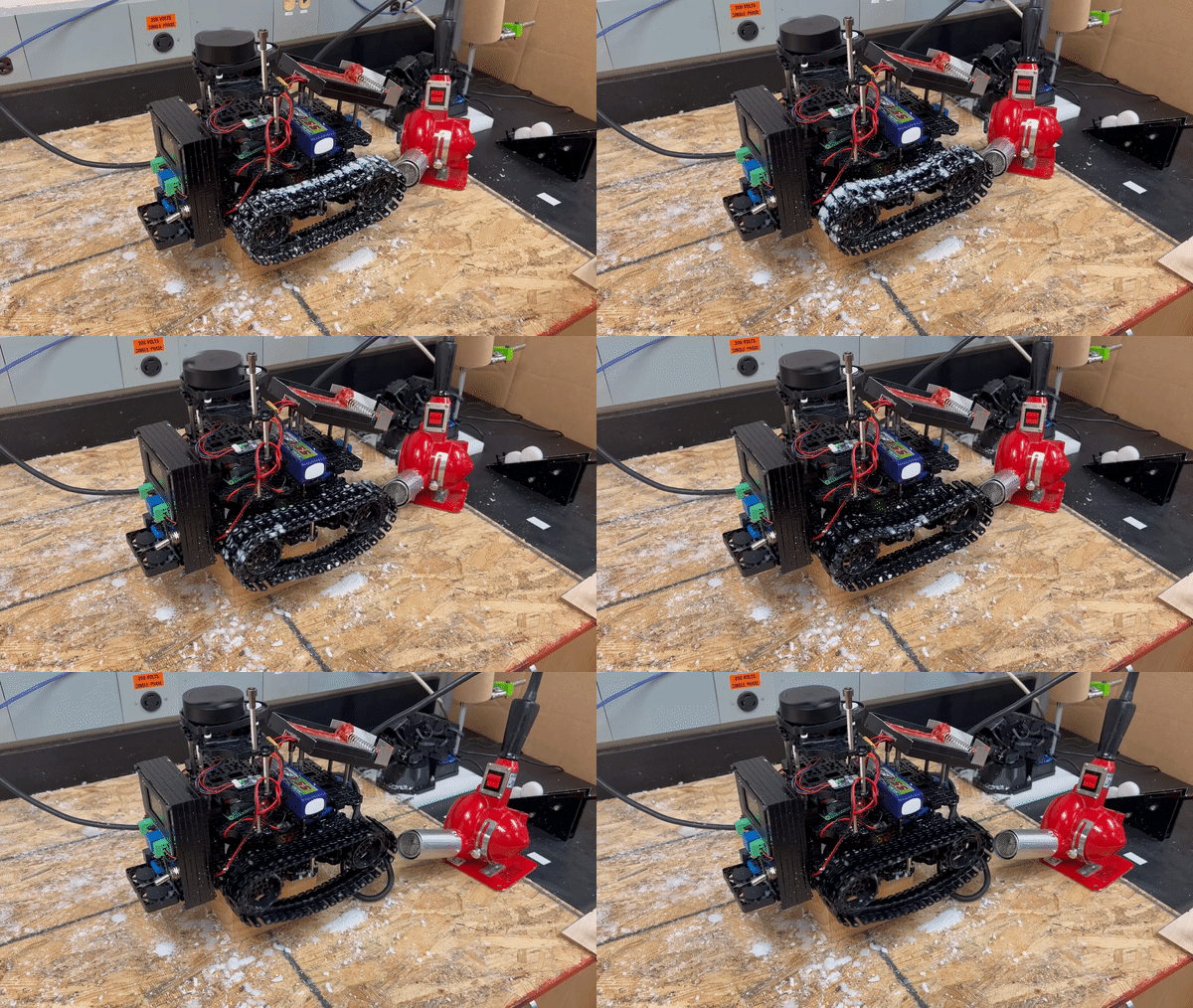
Fig. 18 Self Cleaning